Member Isolation (for adding member views for auto detailing)
Also see :
|
- Detail Members (draws 3D member views in 2D)
- Detail Member Groups (draws 3D member views in 2D)
- Member View Defaults (Home > Project Settings > Fabricator > )
- Preferred bottom flange view style ( Fabricator > Detailing > Member Detailing Settings > " Beams " tab > )
- Member isolation solid display type ( User and Site Options > Modeling > )
- Depth check controls (can change a view's depth check limits, permanently if followed by " Save ")
- Find Material (isolates members in a different way)
- Display Options (isolates members in a different way)
- Status Display (isolates with " None ' and " Masked ')
- Section View (a way to add views in the Drawing Editor )
- Material Drafting (another way to add views in the Drawing Editor )
- Save View As (can be used in member isolation)
- Material Isolation's edit views mode (for adding views to material)
page 1 | contents | member | group member | top
To bring a member or group member into isolation :
Member:
Group member:
Note: Members cannot be brought into isolation until they have undergone Create Solids .
page 1 | contents | member | group member | top
How member isolation relates to detailing :
|
|
|||
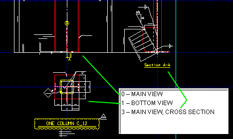
| Views on member isolation's view list are applied to the affected detail when you Detail Members . This illustration shows the three views on a detail along with the view list. |
|
|||
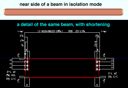
| On a member's 2D detail, the same view view that is shown in isolation may be shortened. Shortening takes place automatically when you Detail Members . |
page 1 | contents | member | group member | top
Examples of preset views :
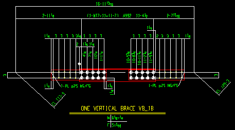
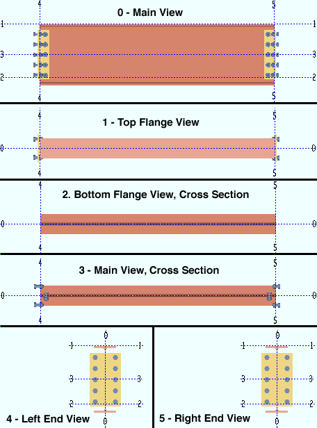
- To create a preset view in member isolation, press the " Preset " button and select an option on the list. Or, at any time in Modeling or the Drawing Editor , you can press the " Add View " button on a member edit window. Any views that you create, including preset views, are automatically drawn in 2D as a part of the member detail (when you Detail Members ). The ability to add views is especially useful for legacy mscellaneous members . Following are some examples of preset views that you can create for a beam:
page 1 | contents | member | group member | top
Tips for creating projected views :
|
Tip 1: If are creating a projected view to replace a preset view, then Delete the preset view first.
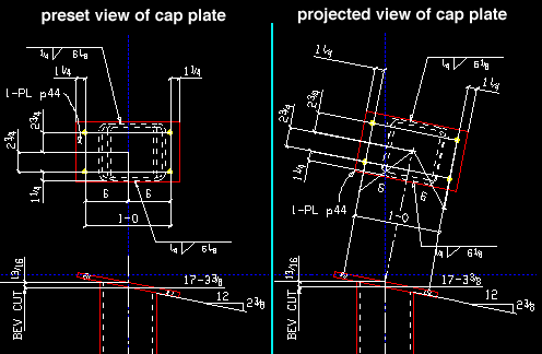
Tip 2: A projected view can be taken from any view (main, top, end, etc.). While in that view, use View > Section View or View > Snap to Adjacent Surface to create an preliminary snapshot of the projected view. The projected view must be perpendicular to your current view.
Tip 3: Set Depth Checking so that the proper perspective is shown in the projected view. In the example above, " In ' was set to the thickness of the plate, while " Out ' was set to 1/16 inch.
Tip 4: Click " Save " when you have the projected view that you want. Press the " Create New " button. Since the view you are saving is perpendicular to the view it was created from, a yes-no dialog opens with the question: " Do you want this view to be a Projected View ?" Be sure to press the " Yes " button if you want a projected view.
Tip 5: After you Detail Members , you may have to clean up the projected view as it is shown on the detail.
page 1 | contents | member | group member | top
Altering the MAIN VIEW of a member :
|
|
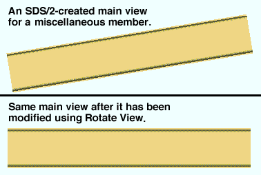
The MAIN VIEW of a legacy miscellaneous member is based on the member's orientation with respect to the view in which it was added. When " Detailed " is set to " In position ' for a legacy miscellaneous member, isolation's main view is the view shown on the detail. Click here for instructions on how to Rotate View . |
On the view list for any member, the main view is named MAIN VIEW . This is true of a miscellaneous member , legacy miscellaneous member or group member or a beam, column, vertical brace or horizontal brace. The main view's number is 0. Generally it is a bad idea to " Delete " a main view, and you are prevented from doing so on members that are not legacy miscellaneous members. However, you can transform the main view of any type of member then Save your changes using the following procedure. Do this procedure before you use " Preset ." Any views that were created based on the previous main view will have to be updated after this procedure.
1 . Begin this operation with a member in isolation.
1a : Double-click MAIN VIEW on the view list .
2 . With the main view of the member shown:
2a : Do whatever view transformations you find are necessary to change how the view is shown. For example, use Rotate View or alter the Depth Checking . For a beam, column or brace, you can use the [0] [-90] [180] [+90] buttons .
3 . Your current view should still be MAIN VIEW.
3a : Press the " Save " button on the Isolate Member toolbox.
Note: This step is important. If you do not " Save " you changes, the view reverts back when you double-click MAIN VIEW .
4 . The Save Member View window opens:

4a : Press the " Save " button. (" New View " causes a new, duplicate main view to be created. " Cancel " brings you back to the beginning of step 3.)
5 . The view that is shown on screen is now the MAIN VIEW for this member.
If you Open another view, then double-click the MAIN VIEW listing , you will get back to this main view saved in step 4..
For a beam, column or brace, you can revert back to the original MAIN VIEW by using " Preset " then checking the box for "
MAIN VIEW ."
Any Preset views that you create from now on are generated with respect to your main view's current orientation.
This MAIN VIEW will be drawn as the main view of the member when you Detail Members (or Detail Member Groups ).
Tip 1: Auto detailing can rotate the main view of a member for you. You should check to see if these options will work for you before you try to change the view in member isolation. The options are found in Home > Project Settings > Fabricator > Member Detaling/Fabrication Options.
| Member Detaling/Fabrication Options | |
| Beam | " Detailed " (" In position ' or " Horizontal ') |
| Column | " Detailed " (" In Position ' or " Horizontal ' or " Vertica l') |
| Vertical Brace | " Detailed " (" In position ' or " Horizontal ') |
| Horizontal Brace | " Detailed " (" In position ' or " Horizontal ') |
| [Legacy]
Miscellaneous |
" Detailed " (" In Position ' or " Horizontal ' or " Vertica l') |
Tip 2: [0] [-90] [180] [+90] buttons can be used to rotate the MAIN VIEW of a beam, column, vertical brace or horizontal brace.
Tip 3: Be sure to adjust a member's MAIN VIEW before you create section views (using " New ") or before you use " Preset ." If you don't do this, the old views will be based off the old MAIN VIEW .
Tip 4: Vews that were created before you changed the MAIN VIEW can be updated by using " New " or " Preset ."
page 1 | contents | member | group member | top
Special considerations for group members :
page 1 | contents | member | group member | top
View list

|
Tip: You can double-click a member view name to open that view without having to press the " Open " button. |
|
page 1 | contents | member | group member | top
Open

1 . Before using this tool, select any name listed in the view list .
2 . Press this button on the Isolate Member toolbox to open the selected view.
Tip: You can double-click a member view name to open that view without having to press the " Open " button.
page 1 | contents | member | group member | top
New

|
Press this button on the Isolate Member toolbox to cut a section view transverse to two points that you locate. You might do this to look at the isolated member from a new perspective, or to create a grid line for the placement of material, or in order to generate the view as a 2D drawing on a member detail created when you Detail Members .
1 . With the member view that you want shown on screen:
1a : Press the " New " button on the Isolate Member toolbox.
2 . Locate- Pan -Return mouse bindings are activated along with various Locate options.
|
|
|
bindings |
2a : Select the Locate icon that you want (if it isn't pressed already).
2b : Place the mouse pointer so that the point location target snaps to a point through which you want the view drawn, then left-click ( Locate ).
3 . The status line prompts, "Locate second point."
|
|
|
bindings |
3a : Left-click ( Locate ) when the point location target is at a second point through which you want the view drawn.
Note: The arrow head that appears as you move the mouse pointer points in the direction you will be looking when you access the view you are creating. Generally you will want the arrow facing toward the material.
4 . The new member view you create appears in your current view as a grid line (a blue line with a number labeled on it). The member view is numbered in the order in which it was created. In the view list , the new view is the last name listed, and it is named " CROSS SECTION (user created) ." Do either of the following:
|
|
|
bindings |
Alternative 1 : Repeat steps 2 and 3 to add more new views.
Alternative 2 : Right-click ( Return ) if you are done adding views.
Warning: Member views created using the above method are automatically incorporated into 2D member details that are generated when you Detail Members . If you don't want this to happen, use Delete to remove them before you press " OK " to exit member isolation.
page 1 | contents | member | group member | top
Preset
 |
| Examples of preset views for a beam are shown above . |
|
Press this button on the Isolate Member toolbox to get a list of preset views that can be automatically generated for you.
For legacy miscellaneous members: When Home > Project Settings > Fabricator > Detailing > Member Detailing Settings > " Detailed " is set to " In position ', isolation's main view is the view shown on the detail, and the preset views are based off of that main view. If " Detailed ' is set to " Horizontal ' or " Vertical ', the main view is always shown flat, and the preset views that are selected are based off of that flat view.
1 . Preset views are based on the MAIN VIEW for all members but group members. For group members, preset views are based on the " Main member ." If you have altered the main view of a member, you must first Save your changes to the main view if you want the preset views to be based off of your altered main view. Step 1a is required for group members -- it does not apply to other members.
1a : For a group member, select the " Main member " that you want to be used for preset views.
1b : Press the " Preset " button on the Isolate Member toolbox.
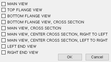
2 . A window opens. On it is a list of preset views that are available for the member type you are viewing.
|
This example shows the preset views that are available for beams. The " BOTTOM FLANGE VIEW " is a "worm's eye view." A related setup option is " Preferred bottom flange view style " in Member Detailing Settings . |
2a : Check the box (
) next to each of the view(s) that you want to include on the detail for this member.
Alternative 1 : Press the " OK " button. Go to step 3 or 4.
Alternative 2 : Press " Cancel " to end this operation. Do not continue.
3 . Skip this step if it does not apply. The Duplicate View dialog opens if you attempted to create a preset view of a type that already exists. The dialog informs you of the type of duplicate view that has been detected and gives you three options for saving your new view:
"Insert" adds the new, duplicate preset view to the view list.
"Replace" replaces the other view of that type that is already on the view list with the new, duplicate view.
"Abort" cancels the adding of the duplicate view.
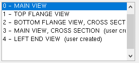
4 . The preset view(s) selected in step 2 are now listed in the view list , after system-created views. The words "(user created)"are written in parentheses after the new view(s).
Note: Member views are automatically incorporated into member details that are generated when you Detail Members (or Detail Member Groups for a group member). For beams, columns and braces with automatically generated connections, any member views necessary for fabrication purposes are automatically generated without your having to generate special user created views. However, for miscellaneous members, legacy miscellaneous members and group members, creating a preset view before auto detailing may be the best way for you to obtain a good detail of that member. Remember (as mentioned above) that preset views are based off of the main view -- you must first Save changes to a main view if you want the preset views to be based off that view.
Also see: Depth checking defaults for preset views are set up in Home > Project Settings > Fabricator > Member View Defaults . You can use depth check controls followed by " Save " to override those depth checking defaults for individual preset views.
page 1 | contents | member | group member | top
Delete

|
Press " Delete " on the Isolate Member toolbox to open a list of member views that you can delete. The main reason to delete a member view is to prevent that view from appearing on a member detail (created when you Detail Members ). If you happen to delete a MAIN VIEW , auto detailing will not be able to generate that member's detail when you Detail Members . To get the MAIN VIEW back, you can create a Preset main view then Process and Create Solids .
1 . Begin this operation with a member of any type in isolation.
1a ( if applicable ): Open a view that is not one of the views you want to delete.
1b : Press the " Delete " button on the Isolate Member toolbox.
2 . The Select View(s) to Delete window opens. On it is a list of all member views of the member you are currently viewing (with the exception of your current view).
2a : Select the member view(s) you want to delete.
2b : Press the " OK " button.
3 . The member views you selected are erased, and you remain in the view that you started in. The remaining views in the list are renumbered in order to preserve the order in which they were added.
Warning: Deleting a member view prevents it from being automatically detailed as a part of 2D detail drawings when you Detail Members . For this reason, you are prevented from deleting main views on beams, columns and braces. You can, however, delete the main view on a legacy miscellaneous member.
page 1 | contents | member | group member | top
Save

Press the " Save " button on the Isolate Member toolbox to save changes made to your current member view under a new name or to save a duplicate view if your current view has not changed. Note: You need to press " Save " in order to retain changes made using " Clip "or " Unclip " or " Depth Checking ."
1 . Before you can Save , you may (optionally) want to first perform an operation on a member view that causes the view to change. Tools that relocate a view include Depth Checking , Rotate View , Snap to Surface , Snap to Farside Surface and Snap to Adjacent Surface . You also need to press " Save " in order to retain changes made using " Clip "or " Unclip ."
1a . Press the " Save " button on the Isolate Member toolbox. Go to step 2 if your current view has not changed. Or go to step 3 if your current view has changed.
2 . Skip this step if it does not apply. If your view has not changed since you originally isolated the member, the " Create Member View " opens.
Alternative 1 : Press the " New View " button to cause a new " Detail VIEW " (that is a duplicate of your current view) to be listed in the view list . Do not continue.
Alternative 2 : Press the " Cancel " button to cancel this operation without creating a new view. Do not continue.
3 . The Save Member View window opens. On it is notification that your current "View has changed!" Press one of the following buttons:

"Save" saves the changes made to your current view. Go to step 4.
"New View" saves your on-screen perspective as a new view. If the new view is perpendicular to the view it was created from, a yes-no dialog opens. On it is the question, " Do you want this view to be a Projected View? " Press the " Yes " button if you want a projected view (right view in the illustration ); press " No " if you want a normal cross section. The view will be listed as a new " Detail VIEW " in the view list . Go to step 4.
"Cancel" ends the save operation and keeps everything as it was before step 1.
4 . The view you started in remains your current view. If you created a view with a new name using this procedure, that view is the last view on the view list and has (user created) written next to it.
Note: The " Save "button on the Isolate Member toolbox does not produce the same results as choosing File > Save View As... . " Save " gives you a member view. Save View As... gives you an erection view.
page 1 | contents | member | group member | top
Save Area

|
Press the " Save Area " button on the Isolate Member toolbox to save an area view that includes your current member plus all adjoining members. This is essentially the same tool as Save Area View when a member is not in isolation. Once this operation is done, you can:
Press " OK " to exit isolation, then Open View ( Ctrl + o ) to look at the view you have created in this manner
Create a 2D drawing of this view using Detail Erection Views .
Delete this view using Delete View .
To do a Save Area :
1 . Begin this operation with a member view shown on screen.
1a : Press the " Save Area " button on the Isolate Member toolbox.
2 . The status line prompts, "Locate area to save." Locate- Pan -Return mouse bindings become active.
|
|
|
bindings |
2a : Hold down the left mouse button ( Locate ) and drag your mouse pointer to form an area box around the members you want to include in the area view.

3 . The member you selected is displayed in the User and Site Options > Modeling > " Primary selection surface color ." The Drawing Editor drawings window opens. On it are the following entry fields:
Detail scale ( Base 12 or Base 10 ): If the words " Base 12 " are in parenthesis, then make your entry in imperial units (X inch = one foot, where X is the number of inches on the drawing that you want to represent 1 foot at the construction site). If the words " Base 10 " are in parenthesis, make your entry in metric units (X mm = 10 mm). The default scale is the " Drawing scale " on the Display Options window for your current erection view (the view that was open when you isolated this member). The value you enter is the scale applied when you first detail this 2D erection view . Subsequent versions of that drawing regenerated from this view use the scale entered to " Drawing scale " on the Drawing Data window.
Drawing name: The name of this view (up to 61 characters). Unless you want this view to overwrite an existing erection view (see below ), you should give this view an original name that has not been given to other views.
Erection view type: Primary or Secondary or Dimension only or Placement only . Select the erection view type based on how you want the view's grid line dimensioned when you Detail Erection Views and choose to " Annotate erection views ." Note: Locate options in Modeling such as INCL or INCM snap to points on erection views of any of these types.
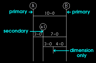
' Primary ' dimensions appear above ' Secondary ' dimensions. ' Dimension only ' erection views are auto dimensioned, but not with grid markers. ' Placement only ' erection views cannot be auto dimensioned (" Annotate erection views "). Pen color: The color of the erection view that Save Area will add. Since the grid line associated with the view added using Save Area will always be a straight grid line , this sets the color of the grid line in Modeling only. Straight grid lines are not generated when you Detail Erection Views . They can be automatically dimensioned on erection view drawings, but they do not themselves appear on the erection view drawings.

Line type: The dash pattern of the erection view that Save Area will add. This sets the dash pattern of the grid line in Modeling only. Grid lines are not generated when you Detail Erection Views .

The button that is pressed sets the line type (dash pattern) of the area view that you are adding.

Alternative 1 : Press " OK " to save the view and go to step 5 (or 6).
Alternative 2 : Press " Cancel " to end the Save Area View operation without creating a new view. Do not continue.
5 . Skip this step if it does not apply. If you typed in the name of a view that already has been created, you get a confirmation dialog with the message, "Do you want replace the existing view?"
Alternative 1 : Press " OK " to replace the view that already has that name with the view you are saving. Go to step 6.
Alternative 2 : Press " Cancel " to end the Save Area operation without creating a new view. Do not continue.
6 . The view you started with in step 1 continues to be displayed on screen. Since you have created an erection view (not a member view) using this tool, the view is not listed in the view list on the Isolate Member toolbox.
page 1 | contents | member | group member | top
Clip

|
Before Clip : 
After Clip : 
Member detail generated after Clip : 
To do a Clip operation:
1 . While looking at a member view that shows the area that you want to clip:
1a : Press the " Clip " button, or click the icon .
2 . Locate- Pan -Return mouse bindings become active.
|
|
|
bindings |
2a : Hold down the left mouse button ( Locate ) and drag the mouse pointer to form an area box around the section of the member you want cut away in the 2D member detail when you Detail Members .
3 . On the Modify View window, do one (1) of the following:

Alternative 1 : Press " Inside " to save the area inside the area box.
Alternative 2 : Press " Outside " to save the areas outside the area box.
Alternative 3 : Press " Cancel " to end the Clip operation without changing anything.
4 . Clip draws a dashed rectangular box around the area that you designated in step 2. Also, one of the following happens:
Possibility 1 : An X is placed inside the region surrounded by the dashed box if you pressed the " Outside " button (in step 3). The X marks the area that will not be drawn on this particular view when you Detail Members and select this member's piecemark.
Possibility 2 : A simple dashed box (without an X in it) is shown if you pressed the " Inside " button (in step 3). The dashed box marks the area that will be drawn on this particular view when you Detail Members and select this member's piecemark.
page 1 | contents | member | group member | top
Unclip

|
|
1 . While looking at a member view that has had a Clip operation performed on it:
1a : Press the " Unclip " button, or click the icon .
2 . Unclip removes the dashed line around the clipped area on the member view.
Note: If you Detailed this member while this member view was clipped, you will have to Detail again in order to have member detailing generate a drawing that includes your current, unclipped member view.
page 1 | contents | member | group member | top
[0] [-90] [180] [+90] buttons

page 1 | contents | member | group member | top
OK

page 1 | contents | member | group member | top

